Firmware Architecture
The Firmware is the software heart of the Flight Controller, executing on its main microcontroller (MCU). It is singularly responsible for the safe and reliable operation of the Unmanned Aerial Vehicle (UAV).
Core Responsibilities
- System State Management -
- Ensuring only valid System State transitions are performed, only after checking guards.
- Enforcing the behavior of the 3 aspects of the System State - Activity, Error and Flight Control Mode.
- Component Management -
- Initializing, reading sensors and processing raw data into pose.
- Managing indicator LEDs.
- Receive and parse data from RC Receiver and Telemetry Radio.
- Flight Stabilization & Control -
- Stabilize UAV based on raw and filtered sensor data.
- Calculate setpoints from RC values based on Flight Control Mode; calculate errors based on current pose and setpoints.
- Calculate motor speed commands from errors and send to ESCs.
- GCS Communication -
- Discover and establish connection with GCS.
- Send/Receive telemetry data from GCS (including RC values, pose, battery level, position etc).
Each of the above responsibilities follows its own sequence of tasks that are governed by their own state (not to be confused with the System State), and their own separate configuration, required resources etc. Yet, they must communicate with each other to maintain the integrity and functionality of the System.
Furthermore, the Firmware must also be portable, as the underlying hardware (MCU and sensors) can greatly vary between Flight Controllers.
Layered Architecture
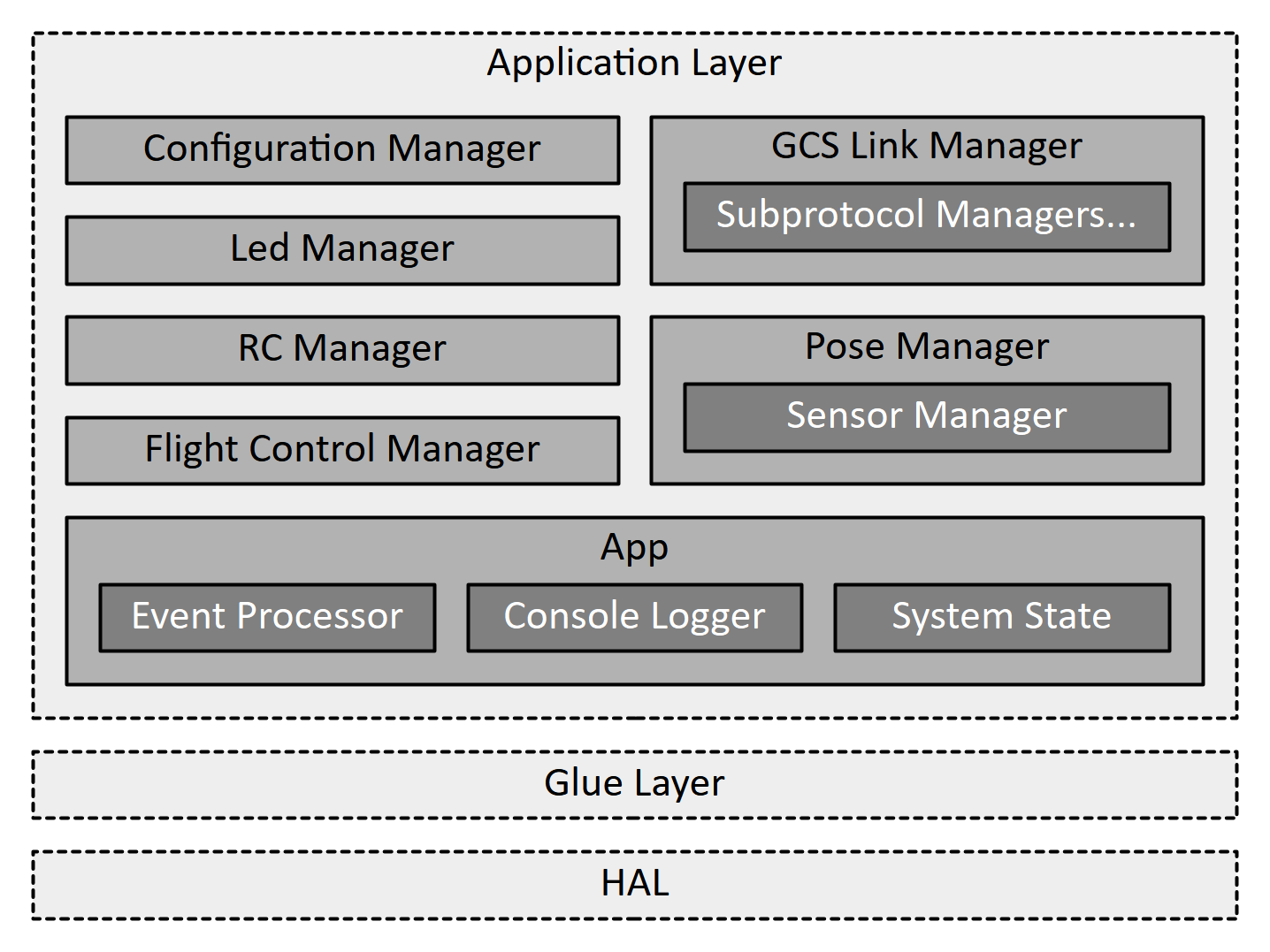
To effectively meet all its requirements, the Firmware is organized into three layers -
- Hardware Abstraction Layer (HAL): This is the lowest layer and includes platform-specific software drivers for interacting with peripherals such as GPIO, Timers, UART, SPI, I2C, DMA and Interrupts Controllers. It also includes the entry-point of the program, and performs peripheral initialization before the Preflight checks can start.
- Glue Layer: This is the middle layer and defines a clear, semantically-named set of interfaces (an API) that the Application Layer uses to perform hardware operations. It acts as a contract between the application and hardware-specific code.
- Application Layer: This is the highest layer, and contains the primary intelligence of the Firmware. It is composed of several "Managers" that handle specific tasks like flight control, communication, sensor management etc.
Let us look at how this pattern handles all the requirements.
Handling Portability
The Glue Layer serves as a central point for all portable code within the Firmware, and the Application Layer (and its sub-components) do not have to understand the hardware; They simply invoke semantically named functions to carry out their objective. These functions are declared in the Glue Layer and implemented in the HAL by using the platform-specific software drivers. Example of this are -
- The Application Layer requires a function to set the PWM pulse on a numbered channel. The details of how this is done is available in the HAL and the Glue Layer defines a function with the appropriate name (e.g.
Glue_PwmSetPulse(channelIndex)) and signature for the Application Layer to use. The Application Layer therefore uses a semantically named interface without understanding its details. The implementation for this (which might include mappingchannelIndexto a GPIO Port, Pin and Timer and atomically updating the timer-overflow register for the combination) given in the HAL using platform-specific drivers. - The Application Layer accepts characters for forming Telemetry messages and provides a function (e.g.
Application_TelemReceive(incomingChar)) that can consume the incoming characters. The Glue Layer provides another similarly named function (e.g.Glue_TelemReceive(incomingChar)) that should be called in the ISR defined in the HAL layer for the UART that the Telemetry Radio is connected to. The ISR can also include other platform-specific code that sets up the interrupt for the next-character, performs error handling etc. in a platform-specific manager.
The first pattern is repeated for all the hardware-access that the Application Layer needs to perform (such as high-resolution timing, sensor communication, GPIO etc.) while the second is repeated for all cases where the hardware needs to send data/notifications to the Application Layer (such as DMA-complete, character received etc.)
This approach allows porting the Firmware to new hardware by simply re-implementing the Glue Layer interfaces and invoking certain functions in ISRs. All the changes are well-defined and restricted to the Glue Layer, which scopes the problem and reduces unexpected errors. The interaction between the Application Layer and Glue Layer is detailed here.
Handling Core Responsibilities
To handle the diverse responsibilities of the Flight Controller along with their specificities, the Application Layer consists of several Managers and a central App object. Since each aspect requires a different set of operations to be performed, resources to be controlled, state etc., the simplest approach is to divide them amongst separate Managers.
Each Manager has its own thread (or multiple threads) with its own state, wait states, error handling and mailbox/fifo for incoming communication, apart from other specific members. Each Manager handles its timing, deadlines, resources on its own. This approach simplifies the execution of asynchronous tasks (such as messaging the GCS, blinking LEDs and reading sensors). Top-level Managers include -
- Configuration Manager: Manages the UAV Configuration being used (load parameters on initialization, store parameters when received from GCS, share changes with other Managers, perform validation of parameters).
- Led Manager: Controlling the state of the indicator LEDs on the Flight Controller (on/off/slow-blink/fast-blink to indicate Activity State, connection, errors).
- RC Manager: Receiving and raw bytes from the RC receiver and forming data-frame containing Pilot commands.
- GCS Link Manager: Transmission and Reception of telemetry messages to synchronize operational data with the GCS, receive UAV configuration etc.
- Pose Manager: Manages the UAV's pose and sensors (sensor initialization, calibration, error-detection and handling, value filtration and fusion).
- Flight Control Manager: Uses Pose, Pilot Commands and Flight Control Mode to run control system (PID, setpoint and errors), calculate and send motor speed commands.
The Managers, however, must also communicate with each other to maintain the System's integrity and functionality. Direct communication poses two important challenges -
- Tracking every Manager from every other Manager, notifications/messages sent and ensuring all side-effects are handled becomes exponentially more challenging as new Managers are added.
- A singular source of truth for the System State is absent. If each Manager keeps their own copy, synchronicity between Managers becomes exponentially more challenging as new Managers are added.
To solve this, Managers communicate centrally with the App object by posting System Events. Each System Event has a type and payload (the structure of the latter is determined by the former). The App defines the structure and kinds of System Events that the Managers adhere to.
System Events are processed in the order of their arrival and have their own specific handlers. The handler keeps track of all the effects a System Event has on the System, and executes their logic. This can include sending notifications/messages to other Managers and/or transitioning the System State. Messages sent from the App can cause the Manager to perform/start performing/stop performing some action (handled differently by each Manager). Managers define the messages they can receive that the App adheres to.
The handlers also keep track of the guards and entry/exit actions for the System State transitions, The System State is owned by the App, who enforces valid transitions and access.
Apart from the above, the App is also responsible for providing hardware-access interfaces to the Managers. These interfaces are in-fact wrappers around the Glue Layer interfaces, and this extra layer of indirection created by the App allows separation of hardware-access logic (in the Glue Layer implementation) and application-level verification (in the App's wrapper). An example of this is the Flight Control Manager trying to set a PWM channel's value to a non-zero amount while the System is Disarmed. The App can add an extra check for this before calling the Glue Layer's interface. The Glue Layer interface does not have to perform any checks (or keep awareness of the System State), and simply executes the logic to set the PWM channel.
Finally, the App is also responsible for implementing non-blocking Console Logging, which the Managers can use for printing critical events/errors as an additional feature to Blackbox logging. This is useful for immediate debugging during both development and operations. In the latter case, it might be used to diagnose repeated failure in the Preflight Checks. It is easier to wire the FC to the GCS and simply view the printed messages over UART, rather than removing the Blackbox and deciphering the logs.
Nested Managers
Managers can contain nested Managers when they have a large set of responsibilities. A Manager M is a good candidate for being nested inside another Manager N if -
- M exclusively communicates with N, i.e. the System Events posted by M solely cause notifications/messages to be sent to N.
- All the messages/notifications sent to M are purely consequences of System Events posted by N, i.e. M only receives communication from N.
- M only accesses the System State in-relation to N.
An example of the above is the Sensor Manager, which is responsible for sensor management, i.e. initialization, calibration, reading, filtering, error handling etc. The values it generates are only ever used by the Pose Manager, who performs pose-estimation through sensor fusion. Furthermore, it receives communication exclusively from the Pose Manager (e.g. read a new value, calibrate sensor, report error, execute routine to fix an error etc.) Therefore, it is easier to nest the Sensor Manager within the Pose Manager.