Functional & Behavioral Specifications
This section details the functional and behavioral specifications of the System, i.e. the capabilities offered to Pilots and Operators and behavior over time to carry out these capabilities.
Functional Details
While briefly listed in the Introduction, a more detailed outline of the System's functions and capabilities is given below -
- Flight Stabilization & Control -
- Stabilizing the UAV while it is airborne, i.e. moving (or remaining stationary) according to the Flight Control Mode and RC commands/GCS commands.
- Manual Flight Control with 6 levels of assistance - Position Hold, Altitude Hold, Self-Level, Rate Control and Horizon.
- Providing and enforcing states for safely going near the UAV, calibration, flying, visual checking of actuators.
- Error Handling & Safety -
- Real-time component monitoring and health-checks to ensure all system components are operational at all times.
- Restricting functionality/triggering failsafe in case of specific errors.
- Ensuring the Geofence, Mission, Home Location displayed on GCS is the same as what the UAV is using at all times.
- Communication & Telemetry Management -
- Presenting Operators with continuous, real-time data from the UAV (e.g. position, attitude, altitude, speed, battery level etc.) through the GCS.
- Monitoring critical UAV parameters and events to generate warnings/alerts for the Operator through the GCS to report situations requiring attention (e.g. low-battery, GPS loss, failsafe activation).
- Configuration & Tuning -
- Allows Operators to modify Control System Parameters (e.g. PID gains) through the GCS and maintain consistency between GCS and FC, synchronizing when necessary.
- Allows Operators to customize the GCS behavior and appearance (e.g. log verbosity, units, theme) to suit user preferences.
- Allows Operators to customize UAV behavior (e.g. maximum speed, maximum altitude, battery threshold) through GCS to match operation guidelines.
- System Setup & Maintenance -
- Perform automatic, thorough preflight checks & calibration upon power-on to verify components and restricting operations in-case of failures.
Modelling the System Through a Finite State Machine
To carry out the above capabilities, the System's behavior is modelled using a finite state machine. The System State describes the current condition of the System, i.e. how it responds to inputs and what decisions it can/will take in the future. It can be used to answer questions of the form -
-
Question 1: Is the UAV ready to be airborne?
Answer: The UAV is ready to be airborne if its Activity State is Active. -
Question 2: Will the UAV respond to Pilot commands?
Answer: The UAV will respond to Pilot Commands if the Flight Control Mode is Manual. -
Question 3: Can the UAV maintain its altitude if it gets windy?
Answer: The UAV will maintain its altitude if it gets windy if the Error State is Normal and/or the Error Flags indicate at least one of the barometers is working. -
Question 4: Can the newly created Geofence on the GCS be safely uploaded to the FC?
Answer: The Geofence can be uploaded to the FC if it is Connected and Disarmed.
To simplify the complex behavior of a UAV, the System State consists of four orthogonal aspects, which together describe the behavior of the System. Transitions in each aspect are handled individually, except for guards which can depend on other aspects. Each state has entry and exit actions and only transitions on specific events.
Modelling and controlling the System's behavior through the above approach (a finite-state machine) has several benefits -
- It is easy for the UAV and FC to agree about the System's current condition. In contrast to this, encoding each aspect through an arbitrary set of variables would make it exponentially more difficult to maintain consistency between the UAV and FC as well as enforce valid conditions.
- It becomes possible to verify and prevent invalid responses and states (e.g. UAV executing RTH Failsafe on GNSS loss, using different Geofence from what is displayed on the GCS etc.)
- A System level summary is visible to the Operator and Pilot through the System State at all times.
Activity State
The Activity State is the aspect of the System State that governs the operational readiness of the UAV. It is the primary state used to reason about the UAV's behavior.
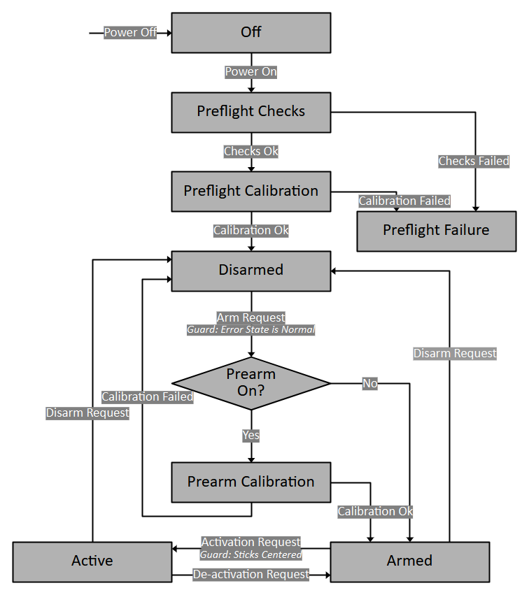
Off
The system is powered down. No operations are active.
Note: This is a logical state, and it does not really exist in the system.
- Entry -
- System is initially Off.
- From all other states via power off.
- Exit: -
- To Preflight upon power up.
Preflight Checks
The system is performing essential system checks after being powered on, and before allowing any potentially hazardous operations.
- Entry -
- From Off state upon power on.
- Exit -
- To Preflight Calibration upon successful completion of all checks.
- To Preflight Failure if any checks fail.
- Behavior -
- Motors are disengaged.
- FC performs automated pre-flight checks (verifying Blackbox status, sensor responses, battery voltage).
- All results are logged to the Blackbox.
- All communication interfaces are initialized and active.
- Direct interaction is not recommended.
Preflight Calibration
The system is performing sensor calibration after checks, and before allowing any potentially hazardous operations.
- Entry -
- From Preflight Checks state upon successful checks.
- Exit -
- To Disarmed upon successful completion of calibration.
- To Preflight Failure if calibration fails.
- Behavior -
- Motors are disengaged.
- FC performs sensor calibration (IMU/Mag bias calculation).
- All results are logged to the Blackbox.
- All communication interfaces are initialized and active.
- Direct interaction is not recommended.
Preflight Failure
To indicate a critical failure during startup preventing safe operation. The UAV should be powered off and the cause of failure should be diagnosed from the logs.
- Entry -
- From Preflight Checks/Preflight Calibration state if checks/calibration fail.
- Exit -
- To Off state upon manual power removal.
- Behavior -
- Motors are disengaged.
- Communication is active.
- Issues are logged to the Blackbox.
Disarmed
A safe, stable state where the UAV is ready for configuration, connection and power removal, but motors are disengaged. If a connection is established, the GCS can modify the UAV Configuration, Geofence and Mission on the UAV.
- Entry -
- From Preflight Calibration state after successful checks and calibration.
- From Armed via Pilot Command.
- From Armed via Failsafe.
- Exit -
- To Armed via Pilot Command, if Prearm Calibration is off and Error State is normal.
- To Prearm Calibration via Pilot Command, provided safety checks pass (Error State is normal) and Prearm Calibration is on.
- To Off via manual power removal.
- Behavior -
- Motors remain disengaged (safe for proximity).
- Sensor measurement and processing is active.
- Control system is inactive.
- Communication system is active.
- GCS upload and modification operations (Geofence, Mission Plan, UAV Configuration) are permitted.
Prearm Calibration
An intermediate state between Disarmed and Armed, where calibration occurs. In long missions, the calibration values can change over time (due to temperature variations, wind etc.) and calibration needs to be performed regularly even after Preflight Calibration. To prevent having to power cycle the UAV, the Prearm Calibration State is used.
- Entry -
- From Disarmed via Pilot Command.
- Exit -
- To Armed if calibration is successful.
- To Disarmed if calibration fails.
- To Off via manual power removal (not recommended).
- Behavior -
- Motors remain disengaged (safe for proximity).
- Sensor measurement and processing is active.
- Control system is refreshed and inactive.
- Communication system is active.
- GCS upload and modification operations (Geofence, Mission Plan, UAV Configuration) are prohibited.
Armed
An intermediate state warming up the motors and control system, allowing visual pre-flight checks by the Pilot before activating full flight capabilities.
- Entry -
- From Disarmed via Pilot Command, provided safety checks pass (Error State is normal) and Prearm Calibration is off.
- From Prearm Calibration via Pilot Command, provided calibration is successful.
- From Active via Pilot Command.
- Exit -
- To Disarmed via Pilot Command.
- To Active via Pilot Command, provided safety checks pass (sticks centered to prevent accidental takeoff).
- To Off via manual power removal (not recommended, switch to Disarmed first).
- Behavior -
- Motors and control surfaces are engaged at minimum power (unsafe for proximity), for visible verification by Pilot.
- Sensor measurement and processing is active.
- Control System is active.
- Communication System is active.
- GCS upload and modification operations (Geofence, Mission Plan, UAV Configuration) are prohibited.
Active
The primary operational state where the UAV is capable of flight (manual or autonomous).
- Entry -
- From Armed via Pilot Command, provided safety checks pass (sticks centered and throttle below midpoint to prevent accidental takeoff).
- Exit -
- To Armed via Pilot Command.
- To Off via manual power removal (not recommended, switch to Disarmed first).
- Behavior -
- Motors and control surfaces are fully active, responding to control system commands (UAV might be airborne).
- Sensor measurement and processing is active.
- Control system is active.
- GCS upload and modification operations (Geofence, Mission Plan, UAV Configuration) are prohibited.
- Flight mode changes commanded via GCS take effect.
- Control System tuning via GCS takes effect.
Error State & Flags
The System's working/failed components are summarized by the Error State and Flags. This is used to restrict transitions in the Activity State and Flight Control Mode, as well as other features such as autonomous operations. It is also used to indicate the UAV's working condition to the Operator so that they make take appropriate decisions on time.
The Error Flags are a set of on/off values, each representing the working condition of a specific subsystem.
In particular, they do not contain the cause, only the present working condition. When the value of one of these flags changes, the system calculates the Error State corresponding to the current values of all the flags and transitions to it if not already in the state and transitioning is allowed.
The Error State is a summary of the Error Flags that the entire system can use to restrict certain functionality or execute a routine.
The failures can be classified into 3 categories -
- Non-severe Failure: Failures that do not compromise the UAV's ability to fly. Examples are non-IMU sensor failure (can be temporary), single IMU failure, over-heating, battery dropping below first threshold etc. They can generally be recovered from during the flight itself.
- Severe Failure: Failures that are mostly not temporary, warrant an immediate response as they can soon lead to the UAV's flight/safety being compromised. Examples include the battery dropping below second threshold. They can generally be recovered from by landing the UAV and fixing the cause.
- Catastrophic Failure: Failures that compromise the UAV's ability to fly and be controlled. Examples includes motor failure, all IMU failure, Blackbox failure. They generally can not be recovered from and cause the UAV to crash.

Normal
The default operational state where no faults are detected. Full functionality corresponding to the current Activity State and Flight Control Mode is available.
Critical
To alert the Operator to non-severe failure before it can lead to safety being compromised, while potentially restricting some non-essential functions.
- Entry -
- From Normal on non-severe failure detection.
- Exit -
- To Normal if the non-severe failure is fixed.
- To Failsafe on severe failure.
- To Emergency on catastrophic failure.
- Behavior -
- UAV remains manually controllable.
- GCS alerts the Operator.
- Depending on Error Flags, certain functionality (such as autonomous missions) can be restricted.
- Once the UAV is Disarmed, transitioning to Armed/Prearm Calibration is restricted.
Failsafe
To autonomously maneuver the UAV to land, following the completion of an RTH, of a severe but potentially recoverable failure, overriding most external commands. The UAV must land and Disarm, and the failure must be diagnosed. After fixing the problem, the UAV can be power cycled to verify if normal operations can begin.
- Entry -
- From Normal/Critical on severe failure detection.
- Exit -
- To Emergency on catastrophic failure.
- Behavior -
- Ignores most Operator, Pilot commands (except Deactivating and Disarming).
- Initiates automatic RTH/Landing (if GPS is available).
Emergency
To signify catastrophic failure where controlled flight is likely lost. The system attempts a best effort landing/disarm but safe recovery is not guaranteed. The area must be evacuated. The logs must be used to diagnose the failure and fix it. After fixing the cause of failure, the UAV can be power cycled to verify if normal operations can begin.
- Entry -
- From Normal/Critical/Failsafe on catastrophic failure detection.
- Exit -
- Only on power off and reset.
- Behavior -
- UAV attempts Landing and Disarm, but without guarantee.
- The Area must be evacuated.
- Control is lost.
Flight Control Mode
Within the Active state, specific flight modes dictate how the UAV responds to commands or navigates autonomously.
Manual
Under the Manual Flight Control Mode, the UAV's movement is controlled by commands sent by the Pilot through the RC. Manual control consists of the following 6 levels of assistance -
Position Hold
Under Position Hold, the sticks control the UAV's 3-dimensional velocity -
- The Roll stick controls the UAV's speed in the lateral axis. Centering the stick results in the UAV resisting external forces in the lateral axis.
- The Pitch stick controls the UAV's speed in the longitudinal axis. Centering the stick results in the UAV resisting external forces in the longitudinal axis.
- The Yaw stick controls the UAV's angular rate in the vertical axis, i.e. the heading. Centering the yaw stick results in the UAV resisting external forces that change its heading.
- The Throttle stick controls the UAV's speed in the vertical axis. Centering the stick results in the UAV resisting external forces in the vertical axis.
Position Hold can be performed using only an IMU (in case other sensors fail), but ideally requires a Magnetometer (for strict heading), Barometer (for strict altitude) and GPS (for strict positioning) for improved accuracy and performance.
Altitude Hold
Under Altitude Hold, the sticks control the UAV's tilt angles in the lateral and longitudinal axis, and the speed in the vertical axis.
- The Roll and Pitch sticks control the UAV's Roll and Pitch angles. Centering the stick results in the UAV remaining horizontal. External forces can drift the UAV from its position.
- The Yaw stick controls the UAV's angular rate in the vertical axis, i.e. the heading. Centering the yaw stick results in the UAV resisting external forces that change its heading.
- The Throttle stick controls the UAV's speed in the vertical axis. Centering the stick results in the UAV resisting external forces in the vertical axis.
Altitude Hold can be performed using only an IMU (in case other sensors fail), but ideally requires a Magnetometer (for strict heading) and Barometer (for strict altitude) for improved accuracy and performance.
Self-Level
Under Self-Level Mode (also known as Angle Mode in many flight control systems), the sticks control the UAV's tilt angles and thrust output.
- The Roll and Pitch sticks control the UAV's Roll and Pitch angles. Centering the stick results in the UAV remaining horizontal. External forces can drift the UAV from its position.
- The Yaw stick controls the UAV's angular rate in the vertical axis, i.e. the heading. Centering the yaw stick results in the UAV resisting external forces that change its heading.
- The Throttle stick controls the UAV's thrust output (motor signal magnitude). Centering the stick results in an arbitrary thrust, and the rate of climb/fall of the UAV depends on the battery level and motor output.
Self-Level Mode can be performed using only an IMU (in case other sensors fail), but ideally requires a Magnetometer (for strict heading) for improved accuracy and performance.
Rate Control
Under Rate Control Mode (also known as Acro Mode in many flight control systems), the sticks control the UAV's angular rates and thrust output.
- The Roll and Pitch sticks control the UAV's Roll and Pitch angular rates. External forces can drift the UAV from its position, or change its attitude.
- The Yaw stick controls the UAV's angular rate in the vertical axis, i.e. the heading.
- The Throttle stick controls the UAV's thrust output (motor signal magnitude). Centering the stick results in an arbitrary thrust, and the rate of climb/fall of the UAV depends on the battery level and motor output.
Rate Control Mode requires only an IMU to work.
Horizon
Under Horizon Mode, the sticks control a blend of tilt angles and angular rates, depending on stick deflection. This allows both stabilized flight and acrobatic control within the same mode.
- The Roll and Pitch sticks control a dynamic blend of tilt angle and angular rate control. When stick deflection is minimal, the UAV operates in Self-Level Mode characteristics. As stick deflection increases, the UAV transitions toward Rate Mode, allowing aggressive acrobatic maneuvers.
- The Yaw stick controls the UAV's angular rate in the vertical axis, i.e. the heading. Centering the yaw stick results in the UAV resisting external forces that change its heading.
- The Throttle stick controls the UAV's thrust output (motor signal magnitude). Centering the stick results in an arbitrary thrust, and the rate of climb/fall of the UAV depends on the battery level and motor output.
Horizon Mode can be performed using only an IMU (in case other sensors fail), but ideally requires a Magnetometer (for strict heading) for improved accuracy and performance.
Connection State
The Connection State is a boolean used to check if a connection exists between the UAV and GCS or not, i.e. have they discovered each other and maintained a link where telemetry messages are being shared. It is primarily used to prevent synchronization of the UAV Configuration and Control System Configuration at invalid times -
- The GCS downloads the UAV Configuration and Control System Configuration from the FC when a connection is established (when the Connection State transitions from Disconnected to Connected). This is to ensure that the Operator starts operations with the correct values displayed on the GCS.
- The GCS UI prevents modification to the UAV Configuration unless the Activity State is Disarmed or the Connection State is Disconnected. This ensures that potentially risky changes to the configuration are not made while the UAV is airborne.
- The GCS UI prevents modification to the Control System Configuration while the Connection State is Disconnected. This is to ensure that changes are only made to the Control System while its response can be observed and do not get missed.
In particular, the UAV Configuration and Control System Configuration have opposite rules for being updated.
The former can only be updated while the UAV is Disconnected/Disarmed to prevent invalid/hazardous conditions (e.g. suddenly reducing the UAV's maximum altitude, causing the UAV to drop; suddenly reducing the battery-threshold that can cause unexpected Failsafe to be triggered).
The latter can only be updated while the UAV is Connected, so that all changes are observed. This prevents cases where the UAV is not responding to changes (while disconnected) and jerks suddenly when a connection is established and a high value is sent to it.